Welcome to RealFlight!
Browse RF Drone Articles by Category
This Knowledge Base contains the articles pertaining to RF Drone. The links below will be used to navigate these items.
Pre-Sales
As with a desktop PC, you must ensure your laptop meets or exceeds all the System Requirements for the version of RealFlight you intend to use. Since RealFlight is 3D accelerated, it is especially important that the display device on your laptop is designed to support graphics-intensive 3D games. Laptops intended for 3D gaming will be built with a video card rather than an integrated graphics processor. Gaming-capable laptops are typically marketed as "gaming laptops" or "multimedia laptops".
For more information regarding the expected performance of your laptop, please contact your laptop manufacturer.
RealFlight is compatible only with Microsoft Windows and cannot be used with Mac OS/OSX operating systems. But if you can run Windows on your Macintosh computer, you should also be able to run RealFlight.
Apple now offers a program called "Boot Camp" that does allow Macintosh users to dual-boot Windows with Mac OS/OSX. For help installing Windows onto your Mac using Boot Camp, contact Apple Support.
An integrated graphics processor is a low power substitute for a video card and is not intended for resource intensive 3D games. Integrated graphics use shared system memory (RAM) for video memory and the central processor (CPU) for graphics processing. A video card has the dedicated video memory (VRAM) and graphics processor (GPU) needed for handling 3D games.
For more information regarding the expected performance of the display device on your laptop or desktop computer, please contact your system manufacturer.
The warranty period for all RealFlight products is 90 days from the date of purchase. The warranty covers product defects and any damage that occurs during shipping and handling from the original purchase.
Please note: The warranty is not transferrable, and does not cover second hand purchases.
Under the terms of the Limited Use Software License Agreement, one copy of RealFlight is licensed for one user. While RealFlight is licensed for one user, that user can definitely have it installed on more than one machine at a time. There is no need to deregister a computer.
In the event the user is not able to activate or register on a second machine, they can contact Software Support to request a registration reset for their number. This will allow them to re-register from the new computer.
Minimum Recommended System
- Operating System: Windows Vista®, 7, 8.x, or 10 (Local administrator access required)
- Processor: Intel Pentium 1.0 GHz or equivalent
- Graphics: 3D accelerated video card with 32 MB of dedicated video memory and full DirectX 9 support (Pixel Shader 2.0)
- Hard Drive Space: 3 GB
- System Memory: 512 MB RAM
- Installation: Internal or External DVD Drive (A downloadable alternative to the installation disk is not available)
Optimal System
- Processor: Dual Core 2.4 GHz CPU
- Graphics: 3D accelerated video card with 512 MB of dedicated video memory (Pixel Shader 3.0)
- System Memory: 2 GB RAM
InterLink Elite Controller:
- USB Port
- Compatible FM or FM-selectable transmitter (if using the interface mode)
- The connectors on the InterLink Elite Controller interface cord and included adapter are compatible with the trainer ports on most Futaba and all JR, Spektrum, and Tower Hobbies systems
Online Activation Required
Installation
A downloadable version of RealFlight Drone is not available. Installation is only supported from an original DVD ROM. To install RealFlight Drone on a computer that does not have a disk drive, you can use an external USB DVD ROM drive. The RealFlight Drone disk is not referenced for daily operation, so you can store the disk once the installation is complete.
This option may be helpful to you: Several users have reported they were able to install RealFlight Drone from a USB flash drive. For that to work, you will need to place the disk contents in the root of the flash drive (do not place the disk contents in a folder). You will also need to rename the flash drive with the same name as the installation disk (RFDRONE_1). If you do try to install RealFlight Drone from a USB flash drive, bear in mind this method is not officially supported.
RealFlight Drone displays an Activation Key on your screen ONLY if the software fails to activate automatically across the Internet.
Please note: If you are able to run RealFlight Drone, the software is already activated. If you are looking to register for access to the program updates, that process is located under the RealFlight Drone Launcher.
If RealFlight Drone fails to activate automatically, a Product Activation window will appear with the information you need to manually activate the software:
RealFlight Serial: XXXXXXXX-RD-XXXXXXXXXX
InterLink Serial: XXXXXXX-I3-XXXXXX
Activation Key: A five- to ten-digit number
With the above information, you can create an Activation Code for RealFlight Drone on the Online Activation page from any computer or smart phone with internet access, or you can forward your information to Horizon Hobby Software Support so we can create an Activation Code for you.
Upgrade/Update
We will need to reset the registration for your copy of RealFlight. Please complete the support request form.
Once your information has been verified, we will reset the registration. You can then re-register with a new password.
Please note: Horizon Hobby can only reset the registration for the current registered owner. If you received RealFlight secondhand, the original owner will need to grant permission to clear his/her information from the registration. Alternatively, we can accept a verifiable receipt for a secondhand purchase (handwritten receipts cannot be accepted).
You must register from your current installation before you can update. The registration and updating processes are located on the RealFlight Drone Launcher:
- Open the RealFlight Drone Launcher.
- Select Additional Options.
- Select Registration/Updates.
- From the Online Updating window, select Online Registration.
- Complete all required fields on the Registration Information form and enter a password (twice) at the bottom.
- Select Send Information to complete the registration process.
- You should receive a confirmation that says, "Thank you for registering this software…". Click OK from that message.
- You can now select Update to Latest Version from the Online Updating window to begin the update process.
A RealFlight Drone upgrade is not offered.
Graphical
An integrated graphics processor is a low power substitute for a video card and is not intended for resource intensive 3D games. Integrated graphics use shared system memory (RAM) for video memory and the central processor (CPU) for graphics processing. A video card has the dedicated video memory (VRAM) and graphics processor (GPU) needed for handling 3D games.
For more information regarding the expected performance of the display device on your laptop or desktop computer, please contact your system manufacturer.
If the aircraft and flying fields appear as a red and blue shifted double image, your video card is displaying in Stereoscopic 3D rather than standard 3D.
Stereoscopic 3D is an option found on many high-end video cards, and is intended for use with 3D glasses. Stereoscopic 3D creates an extra level of immersion similar to 3D movies. When you view a 3D game in Stereoscopic 3D without the proper glasses, you will see a red and blue shifted double image. Standard 3D is what you see with more traditional 3D games where no special glasses are required.
If you are using a GeForce video card, you can toggle Stereoscopic 3D off using the Ctrl + T keystroke while RealFlight (or any 3D game) is running.
If Ctrl + T does not turn off the effect you are seeing, please contact Horizon Hobby Software Support for further assistance.
Transmitter
Summary
The following is a description for how to assemble an adapter cord to connect a Multiplex transmitter with the parallel port transmitter interface and the InterLink controller for RealFlight. For all instructions, reference the diagram below.
Resolution
Necessary Components
- One 5-pin round male connector compatible with Multiplex transmitter trainer jacks. This should be very similar in style to the plug used on Multiplex trainer cords.
- One female mono plug receptacle, compatible with the dimensions shown for the "RealFlight Interface Output Connector" as shown in the diagram. NOTE: it is important that the female receptacle has an inner diameter of 3.5mm, a depth of 14mm at the tip, and a depth no greater than 8mm for the base.
- Adequate wiring to connect both jacks together. Wire should be copper, having a high strand count. Do not use single strand wire. Two conductors will be required; one conductor for signal connections, one conductor for ground connections.
- Large and small shrink tubing
- Wire strippers
- 60/40 rosin-core electrical solder
- A 40-watt soldering iron
Assembly Instructions
- Cut each conductor to approximately 8 inches in length.
- Strip approximately 1/4 inch of insulation away from each end of each conductor. Twist the bare strands of wire tightly on each wire end.
- Cut enough pieces of shrink tubing to completely cover each solder connection. Make sure to slide the tubes over the wire ends BEFORE making solder connections.
- "Tin" each end of bare wire with 60/40 rosin-core solder and a hot soldering iron. This is simply to apply a small amount of solder onto the bare wire end to prepare it for soldering onto the jacks.
- "Signal" connection:
- Solder one end of the signal wire to pin #4 on the "trainer jack plug". IMPORTANT: this is the pin located at the 2 o'clock position when looking at the end of the plug itself, as shown in the diagram.
- Solder the other end of the signal wire to the center connection on the "female mono plug receptacle".
- "Ground" connection:
- Solder one end of the ground wire to pin #2 on the "trainer jack plug". IMPORTANT: this is the pin located at the 12 o'clock position when looking at the end of the plug itself, as shown in the diagram.
- Solder the other end of the ground wire to the outside connection on the "female mono plug receptacle".
- Slide all shrink tubes over their respective connections. Apply heat with a heat gun or hair dryer to shrink the tubing over the entire solder connection. This will provide a good electrical insulator for the solder connections, and a good strain relief for the physical connection.
InterLink
Resolution
The serial number for the USB InterLink Controller is located on the actual InterLink itself. Looking at the rear of the controller, you will find it on the smaller white label towards the bottom of the controller below the interface port.
Summary
The following is instruction to change a Mode 1 RealFlight InterLink Controller to Mode 2.
Resolution
Tools Needed
- Medium Phillips-head screwdriver
- Hemostats (preferred), or needle nose pliers
Instructions
Please read all instructions carefully before you begin this conversion. Horizon Hobby will not accept responsibility for incidental damage to your InterLink controller or personal computer as a result of failure to adhere to these instructions properly. Please contact RealFlight Support prior to performing this conversion if you have any questions about this procedure.
- Make sure your RealFlight InterLink Controller is completely disconnected from your computer. Failure to do so could result in permanent damage to your InterLink and/or your computer.
- Remove the four screws from the rear of the controller, remove the case rear half, and lay the controller face-down on your workspace.
- Remove the silver metal ratchet lever and screw from the gimbal on the left-hand side. This is the throttle ratchet. Physically relocate it to the gimbal on the right-hand side. Rotate the metal ratchet 180 degrees, so the screw hole is now on the bottom right side of the gimbal, and the ratchet end is now pointing upward nearest the switch on the top right side, and resting on the ribbed surface of the gimbal. Line up the lever's hole over the plastic mounting stud on the gimbal, insert the screw and tighten to a snug fit (making sure the lever maintains proper alignment over the ribbed area of the gimbal). DO NOT OVERTIGHTEN, as the plastic gimbal may become easily stripped
- On the right-hand gimbal, notice there is an arm-and-spring type lever mounted vertically along the inner-left side of the gimbal, the spring attached at the lower end to a plastic mounting stud. This arm and spring assembly must now be moved to the left-hand gimbal. Using pliers, gently pry the head of the spring upwards off of the plastic arm. Now remove the spring and arm from the gimbal (this may require slight maneuvering of the parts to get them out from behind the main body of the gimbal). NOTE: Pivot the arm outward, then slide to the side to remove it from the gimbal.
- Looking at the left-hand gimbal from the back, on the inner-right side, notice similar arm and spring mounting lugs as were on the other gimbal, except the spring lug is now on the top end and the pivot arm lug is on the bottom end. Take the arm just removed from the other gimbal, insert the pivot end onto the round pivot lug on the lower inside part of this gimbal and rotate the arm upward over the gimbal. With pliers or hemostat, grab one end of the spring which was removed from the other gimbal. Insert the spring down into the gimbal so the loop on the opposite end hooks onto the plastic lug located on the inside top-end of the gimbal. Once hooked, gently pull the opposite end of the spring outward and loop it over the end of the plastic arm. If any question arises to the assembly of the arm and spring assembly, refer to the arm already in place on the bottom of the gimbal as they are assembled in the same manner.
- Both gimbals are now in the Mode 2 configuration. No alteration of any wires is necessary. Reinstall the rear of the case onto the front half and re-install the four case screws.
- Simply enter the RealFlight program and check the configuration of the software to operate in the Mode 2 setting. This is found in the Controller Calibration dialog in the Options menu. No change to the Stick Mapping should be necessary to Mode 2.
Summary
The following is a description for how to assemble an adapter cord to connect a Multiplex transmitter with the parallel port transmitter interface and the InterLink controller for RealFlight. For all instructions, reference the diagram below.
Resolution
Necessary Components
- One 5-pin round male connector compatible with Multiplex transmitter trainer jacks. This should be very similar in style to the plug used on Multiplex trainer cords.
- One female mono plug receptacle, compatible with the dimensions shown for the "RealFlight Interface Output Connector" as shown in the diagram. NOTE: it is important that the female receptacle has an inner diameter of 3.5mm, a depth of 14mm at the tip, and a depth no greater than 8mm for the base.
- Adequate wiring to connect both jacks together. Wire should be copper, having a high strand count. Do not use single strand wire. Two conductors will be required; one conductor for signal connections, one conductor for ground connections.
- Large and small shrink tubing
- Wire strippers
- 60/40 rosin-core electrical solder
- A 40-watt soldering iron
Assembly Instructions
- Cut each conductor to approximately 8 inches in length.
- Strip approximately 1/4 inch of insulation away from each end of each conductor. Twist the bare strands of wire tightly on each wire end.
- Cut enough pieces of shrink tubing to completely cover each solder connection. Make sure to slide the tubes over the wire ends BEFORE making solder connections.
- "Tin" each end of bare wire with 60/40 rosin-core solder and a hot soldering iron. This is simply to apply a small amount of solder onto the bare wire end to prepare it for soldering onto the jacks.
- "Signal" connection:
- Solder one end of the signal wire to pin #4 on the "trainer jack plug". IMPORTANT: this is the pin located at the 2 o'clock position when looking at the end of the plug itself, as shown in the diagram.
- Solder the other end of the signal wire to the center connection on the "female mono plug receptacle".
- "Ground" connection:
- Solder one end of the ground wire to pin #2 on the "trainer jack plug". IMPORTANT: this is the pin located at the 12 o'clock position when looking at the end of the plug itself, as shown in the diagram.
- Solder the other end of the ground wire to the outside connection on the "female mono plug receptacle".
- Slide all shrink tubes over their respective connections. Apply heat with a heat gun or hair dryer to shrink the tubing over the entire solder connection. This will provide a good electrical insulator for the solder connections, and a good strain relief for the physical connection.
Resolution
Batteries are not needed to operate the USB Controller that is included with your RealFlight software. The controller is made using the case from an actual R/C transmitter, giving it a more realistic feel. The computer provides the power for the controller.
The InterLink Elite Controller does not require batteries. The battery door is there only to complete the look and feel of a real R/C transmitter.
Compatibility
As with a desktop PC, you must ensure your laptop meets or exceeds all the System Requirements for the version of RealFlight you intend to use. Since RealFlight is 3D accelerated, it is especially important that the display device on your laptop is designed to support graphics-intensive 3D games. Laptops intended for 3D gaming will be built with a video card rather than an integrated graphics processor. Gaming-capable laptops are typically marketed as "gaming laptops" or "multimedia laptops".
For more information regarding the expected performance of your laptop, please contact your laptop manufacturer.
RealFlight is compatible only with Microsoft Windows and cannot be used with Mac OS/OSX operating systems. But if you can run Windows on your Macintosh computer, you should also be able to run RealFlight.
Apple now offers a program called "Boot Camp" that does allow Macintosh users to dual-boot Windows with Mac OS/OSX. For help installing Windows onto your Mac using Boot Camp, contact Apple Support.
An integrated graphics processor is a low power substitute for a video card and is not intended for resource intensive 3D games. Integrated graphics use shared system memory (RAM) for video memory and the central processor (CPU) for graphics processing. A video card has the dedicated video memory (VRAM) and graphics processor (GPU) needed for handling 3D games.
For more information regarding the expected performance of the display device on your laptop or desktop computer, please contact your system manufacturer.
| EP 1 | EP 2 | EP 3 | EP 4 | EP 5 | EP 6 | EP 7 | EP 8 | |
|---|---|---|---|---|---|---|---|---|
| RealFlight Classic | N | N | N | N | N | N | N | N |
| RealFlight Deluxe | N | N | N | N | N | N | N | N |
| R/C Pilot | N | N | N | N | N | N | N | N |
| RealFlight G2 | N | N | N | N | N | N | N | N |
| RealFlight G2 Lite | N | N | N | N | N | N | N | N |
| RealFlight NexSTAR | N | N | N | N | N | N | N | N |
| RealFlight NexSTAR EP | N | N | N | N | N | N | N | N |
| RealFlight G3.x | C | C | C | C | N | N | N | N |
| RealFlight G4.x | C | C | C | C | C | C | N | N |
| RealFlight Basic | N | N | N | N | N | N | N | N |
| RealFlight G5.x | C | C | C | C | C | C | C | C |
| RealFlight 6.x | C | C | C | C | C | C | C | C |
| RealFlight 7.x | C | C | C | C | C | C | C | C |
| RealFlight 8.x | C | C | C | C | C | C | C | C |
| RealFlight 9.x | C | C | C | C | C | C | C | C |
| RealFlight Drone | N | N | N | N | N | N | N | N |
| RF-X | N | N | N | N | N | N | N | N |
The Expansion Packs are not interdependent. They can be installed in any order or combination into a compatible version of RealFlight.
| AOV 1 | AOV 2 | AOV 3 | AOV 4 | AOV 5 | |
|---|---|---|---|---|---|
| RealFlight Classic | C | C | C | C | N |
| RealFlight Deluxe | C | C | C | C | N |
| R/C Pilot | N | N | N | N | N |
| RealFlight G2 | C | C | C | C | C |
| RealFlight G2 Lite | C | C | C | C | C |
| RealFlight NexSTAR | N | N | N | N | N |
| RealFlight NexSTAR EP | N | N | N | N | N |
| RealFlight G3.x | C | C | C | C | C |
| RealFlight G4.x | N | N | N | N | N |
| RealFlight Basic | N | N | N | N | N |
| RealFlight G5.x | N | N | N | N | N |
| RealFlight 6.x | N | N | N | N | N |
| RealFlight 7.x | N | N | N | N | N |
| RealFlight 8.x | N | N | N | N | N |
| RealFlight 9.x | N | N | N | N | N |
| RealFlight Drone | N | N | N | N | N |
| RF-X | N | N | N | N | N |
The Add-Ons Volume disks are not interdependent. They can be installed in any order or combination into a compatible version of RealFlight.
Please Note: The aircraft and airports from Add-Ons Volumes 1-5 were re-developed for compatibility with RealFlight G4.x, G5.x, 6.x, 7.x, and 8.x. That content is now available as a free download.
| Airplane Mega Pack | |
|---|---|
| RealFlight Classic | N |
| RealFlight Deluxe | N |
| R/C Pilot | N |
| RealFlight G2 | N |
| RealFlight G2 Lite | N |
| RealFlight NexSTAR | N |
| RealFlight NexSTAR EP | N |
| RealFlight G3.x | N |
| RealFlight G4.x | N |
| RealFlight Basic | N |
| RealFlight G5.x | N |
| RealFlight 6.x | C |
| RealFlight 7.x | C |
| RealFlight 8.x | C |
| RealFlight 9.x | C |
| RealFlight Drone | N |
| RF-X | N |
| Helicopter Mega Pack | |
|---|---|
| RealFlight Classic | N |
| RealFlight Deluxe | N |
| R/C Pilot | N |
| RealFlight G2 | N |
| RealFlight G2 Lite | N |
| RealFlight NexSTAR | N |
| RealFlight NexSTAR EP | N |
| RealFlight G3.x | N |
| RealFlight G4.x | N |
| RealFlight Basic | N |
| RealFlight G5.x | N |
| RealFlight 6.x | C |
| RealFlight 7.x | C |
| RealFlight 8.x | C |
| RealFlight 9.x | C |
| RealFlight Drone | N |
| RF-X | N |
| InterLink Elite Controller | |
|---|---|
| RealFlight Classic | N |
| RealFlight Deluxe | N |
| R/C Pilot | N |
| RealFlight G2 | N |
| RealFlight G2 Lite | N |
| RealFlight NexSTAR | N |
| RealFlight NexSTAR EP | N |
| RealFlight G3.x | N |
| RealFlight G4.x | C |
| RealFlight Basic | N |
| RealFlight G5.x | C |
| RealFlight 6.x | C |
| RealFlight 7.x | C |
| RealFlight 8.x | C |
| RealFlight 9.x | C |
| RealFlight Drone | C |
| RF-X | C |

HowTo
Summary
Windows Explorer is one key application with which you should familiarize yourself. This article will briefly describe how to use Windows Explorer. If you are new to the Windows Operating system or to computers in general, it is strongly suggested that you purchase a 'How to' book at your local bookstore. This material will more than likely explain the software in greater detail.
What is Windows Explorer?
Windows Explorer offers you a fast, easy way to view, copy, delete, move, etc., the folders and files found on all of your disk drives. Think of it as one really big filing cabinet. It is important to note that the Windows Explorer application is different from Internet Explorer. Windows Explorer lets you play with the files on your computer, while Internet Explorer allows you to connect to other computers via the World Wide Web.
How to open Windows Explorer
For Windows 95, 98, and ME:
- Click the Windows Start button, and then select the Programs button.
-
Click on Windows Explorer.
For Windows 2000 and XP:
-
Click the Windows Start button, and then select the Programs button.
-
Select the Accessories button.
-
Click on Windows Explorer.
For Windows Vista and 7:
-
Click the Windows logo in the task bar at the lower left.
-
Click Computer from the menu that appears.
What are Drives, Folders and Files?
For organizational purposes, everything on your computer is reduced or segmented into very specific parts and locations. Your PC also consists of drives which are further broken down into Hard Drive(s), CD-ROM drives, floppy drives, ZIP drives (if applicable) and so forth. Within each Drive, there are hundreds, and potentially thousands of Folders and Files. Again, each of these files and folders are of great assistance in keeping things orderly.
A Folder is very similar to a folder in a file cabinet. Inside each of the Folders, there may very well be more sub-folders, or Files. Folders are a great way to keep you organized on different projects that you may be involved with. For example, you might have a Folder for all of your documents, and another for all of your spreadsheets. Furthermore, you may have sub-folders within these to keep those documents even more organized.
Each individual document and spreadsheet within is known as a File. Files are the items that you are able to view and to work on if desired. Examples include images you download from your digital camera, or Word documents you've created.
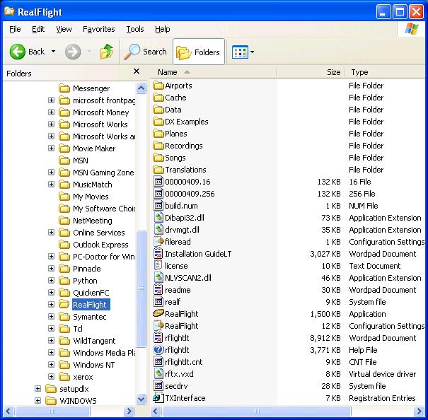
What's inside all these folders?
When you open Windows Explorer, you will see two sections, a left 'pane' and right 'pane'. The left pane shows you your drives and folders. This layout is called a tree, as it closely resembles a tree with all of the 'branches'. To the left of each of the drives is a small [+] symbol. Using the mouse and clicking on this symbol will show you all the folders that are stored on that particular drive. Some of these folders themselves will also have a [+] symbol next to them. Again, this means that there are more sub-folders contained within that particular folder. If you click on the [+], it will open the folder list to reveal the contents and change the [+] to a minus [-] symbol. This simply means that the folder has been opened accordingly. If you click the [-] then it will close the folder and return it to the [+] symbol.
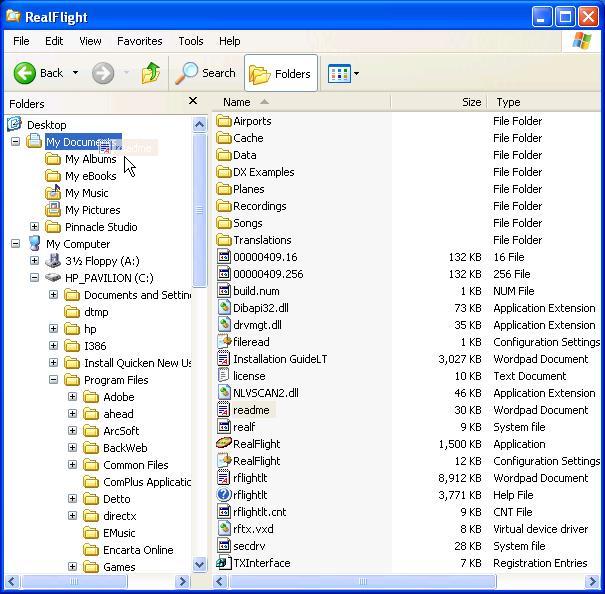
The right pane shows all the files and sub-folders that are contained within the folder that you are currently viewing with Explorer. For example, let's view the contents of the My Documents folder. Generally speaking, this folder is contained on the 'C:' drive of your PC. As such, locate your 'C:' drive in the left pane, click the [+] next to this drive- remember, if it's already opened, it will have a [-] next to it. From the folders listed in the 'C:' drive, locate the My Documents folder. Click on the Folder itself, not the [+] symbol next to it. This will change the contents of the right pane to display all of the sub-folders and files in My Documents.
Opening a file
It is important to note that your computer contains two vastly different types of files. There are Program files and Data files. Program files are the applications that you run on your computer. Examples of Program files include RealFlight and Windows Explorer itself. Data files, on the other hand, contain information that was created by the Program files. These might include text documents, photos or images and music. To open a Program file, simply point the mouse cursor on the file, and click twice (double-click) with the left mouse button. As an example we'll open RealFlight using Windows Explorer:
On the left pane, locate the hard drive that contains the RealFlight program. Generally, this is the 'C:' drive. Click the [+] symbol next to this drive. Again, if it shows the [-] symbol there is no need to click on it as the drive is open.
On the left pane below your hard drive, search for a folder labeled Program Files and click the [+] next to it. This will reveal the contents of the Program Files. Looking at the left pane below the Program Files listing locate a folder that has been designated as RealFlight. To open the RealFlight files, simply click the folder to access its contents. There is no need to click the [+]. The right pane will now display everything that is located in the RealFlight folder. Look for a file titled RealFlight that includes the same icon as the one that appears on your desktop. If you wish to start the RealFlight software, double-click this folder.
Data files are opened in exactly the same way. The only difference is that Windows will first open the application that is needed to view the data file. That is, you do not need to do this yourself. Again using RealFlight as an example, let's open the readme file that appears in the RealFlight folder.
Move or Copy a File
The simplest and most efficient way to move or copy a file is to use your mouse to drag it to the desired location. Moving a file is defined as taking the file out of one folder and placing it into a different folder. Copying, on the other hand, keeps the original file in its current or existing folder and makes an additional 'copy' in the new or target folder.
To move a file:
Locate the file you wish to move on the right pane.
Scroll the left pane so that the target folder or desired location appears. In other words, you are able to see the folder in which you wish to move the file. Click and hold down the left mouse button on the file you wish to move. With the mouse button still held down, move the mouse cursor to the target folder. While you are doing so, a faint image of the icon should now appear with the mouse cursor. When the target folder is highlighted, release the mouse button. This will move the file from its current location to the new desired location. Holding down the mouse button while moving the cursor is called 'dragging the mouse'.
The file you moved should now appear in the new folder.
To copy a file:
To copy a file, follow the same steps as above for moving a file, but this time, hold down the Ctrl key on the keyboard while you are dragging the file.
The same steps can also be used for copying and moving folders themselves. When you copy or move a folder, everything in the folder, including files and sub-folders, are also transferred as well.
This article only briefly discusses what you can do with Windows Explorer. There are many, many additional features and functions offered by this application. If you are new to computers, or to Windows, or if you would simply like to investigate the functionality of this program, it is highly recommended that you check out your local bookstore for more reference.
Creating a new Folder
On the Menu bar, click File, then select New and finally click Folder and the folder will be created in the right hand pane. At this point, the new folder will be created and the name will be highlighted. Type in the name you wish to call the new folder. Make sure prior to making the new folder that you are located at the proper place in the hierarchical view in the left pane. The new folder will always be created as a subfolder of whatever location you have selected.

Drivers are the software installed to support the hardware on your computer (e.g. video card or sound card). The drivers for your computer are not supported through Horizon Hobby.
If you need to update a driver for your computer, please contact your computer manufacturer’s technical support.
You can assemble your system information through the RealFlight Launcher. Here is the procedure:
- Open the RealFlight Launcher.
- Select Additional Options.
- Select Technical Support (please allow several seconds for the Technical Support window to open).
- In the upper right of the Technical Support window, place a check mark next to "Include serial numbers in assembled system information…".
- On the lower right of the Technical Support window, select Assemble System Information.
- From the launcheroutput.txt window, select Copy to Clipboard.
- Paste the launcheroutput.txt information into a simple text file (Microsoft's Notepad works best).
- Attach the launcheroutput.txt text file to your email correspondence with technical support.
Summary
The following is instruction to change a Mode 1 RealFlight InterLink Controller to Mode 2.
Resolution
Tools Needed
- Medium Phillips-head screwdriver
- Hemostats (preferred), or needle nose pliers
Instructions
Please read all instructions carefully before you begin this conversion. Horizon Hobby will not accept responsibility for incidental damage to your InterLink controller or personal computer as a result of failure to adhere to these instructions properly. Please contact RealFlight Support prior to performing this conversion if you have any questions about this procedure.
- Make sure your RealFlight InterLink Controller is completely disconnected from your computer. Failure to do so could result in permanent damage to your InterLink and/or your computer.
- Remove the four screws from the rear of the controller, remove the case rear half, and lay the controller face-down on your workspace.
- Remove the silver metal ratchet lever and screw from the gimbal on the left-hand side. This is the throttle ratchet. Physically relocate it to the gimbal on the right-hand side. Rotate the metal ratchet 180 degrees, so the screw hole is now on the bottom right side of the gimbal, and the ratchet end is now pointing upward nearest the switch on the top right side, and resting on the ribbed surface of the gimbal. Line up the lever's hole over the plastic mounting stud on the gimbal, insert the screw and tighten to a snug fit (making sure the lever maintains proper alignment over the ribbed area of the gimbal). DO NOT OVERTIGHTEN, as the plastic gimbal may become easily stripped
- On the right-hand gimbal, notice there is an arm-and-spring type lever mounted vertically along the inner-left side of the gimbal, the spring attached at the lower end to a plastic mounting stud. This arm and spring assembly must now be moved to the left-hand gimbal. Using pliers, gently pry the head of the spring upwards off of the plastic arm. Now remove the spring and arm from the gimbal (this may require slight maneuvering of the parts to get them out from behind the main body of the gimbal). NOTE: Pivot the arm outward, then slide to the side to remove it from the gimbal.
- Looking at the left-hand gimbal from the back, on the inner-right side, notice similar arm and spring mounting lugs as were on the other gimbal, except the spring lug is now on the top end and the pivot arm lug is on the bottom end. Take the arm just removed from the other gimbal, insert the pivot end onto the round pivot lug on the lower inside part of this gimbal and rotate the arm upward over the gimbal. With pliers or hemostat, grab one end of the spring which was removed from the other gimbal. Insert the spring down into the gimbal so the loop on the opposite end hooks onto the plastic lug located on the inside top-end of the gimbal. Once hooked, gently pull the opposite end of the spring outward and loop it over the end of the plastic arm. If any question arises to the assembly of the arm and spring assembly, refer to the arm already in place on the bottom of the gimbal as they are assembled in the same manner.
- Both gimbals are now in the Mode 2 configuration. No alteration of any wires is necessary. Reinstall the rear of the case onto the front half and re-install the four case screws.
- Simply enter the RealFlight program and check the configuration of the software to operate in the Mode 2 setting. This is found in the Controller Calibration dialog in the Options menu. No change to the Stick Mapping should be necessary to Mode 2.
Drivers are the software installed to support the hardware on your computer (e.g. video card, sound card). The drivers for your computer are not supported through Horizon Hobby.
If you need to repair (e.g. uninstall/reinstall) a driver for your computer, please contact your computer manufacturer's technical support.
To restore the default settings for RealFlight Drone, follow this procedure:
- Open the RealFlight Drone Launcher.
- Select Additional Options.
- Select Restore Defaults.
- Click Yes to the Restore Defaults prompt.
- Run RealFlight Drone. The simulation will launch with the default program settings.
Software Support hours of operation: 8am-6pm Central Time, Monday-Friday.
Email: Please use our contact form.
Mailing Address:
Horizon Hobby
Software Support
1608 Interstate Drive
Champaign, IL 61822
Other
"Dual Rates" refer to altering the rate of servo travel for a control surface on R/C aircraft (e.g. Ailerons, Elevator, and sometimes Rudder). Dual Rates consist of Low Rates and High Rates. Low Rates make the aircraft less responsive (i.e. easier to control), and High Rates make the aircraft more responsive (i.e. harder to control). Dual Rates are typically controlled by a toggle switch on an R/C transmitter.
In RealFlight, the aircraft control surfaces can be set up with Dual Rates. The switch you use to select Low Rates or High Rates depends on the controller or R/C transmitter you are using and personal preference. It is also possible to use a key on your keyboard to control Dual Rates. However, doing so is not realistic to R/C aviation.
Please note: Dual Rates are configured separately for each aircraft.
We will need to reset the registration for your copy of RealFlight. Please complete the support request form.
Once your information has been verified, we will reset the registration. You can then re-register with a new password.
Please note: Horizon Hobby can only reset the registration for the current registered owner. If you received RealFlight secondhand, the original owner will need to grant permission to clear his/her information from the registration. Alternatively, we can accept a verifiable receipt for a secondhand purchase (handwritten receipts cannot be accepted).
Yes. It is in PDF format, so you may need to get Adobe Acrobat Reader DC software in order to view it.
If you would like to print all or part of the RealFlight Drone Manual, you can do so with your local printer.
Software Support hours of operation: 8am-6pm Central Time, Monday-Friday.
Email: Please use our contact form.
Mailing Address:
Horizon Hobby
Software Support
1608 Interstate Drive
Champaign, IL 61822
The warranty period for all RealFlight products is 90 days from the date of purchase. The warranty covers product defects and any damage that occurs during shipping and handling from the original purchase.
Please note: The warranty is not transferrable, and does not cover second hand purchases.